
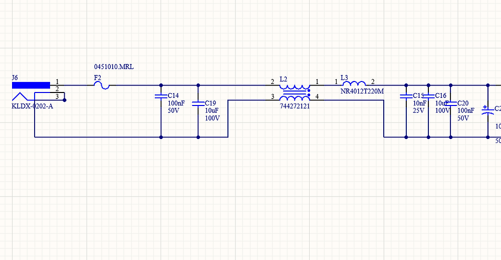
This is one of the most common layout mistakes I see during EMC reviews.
The schematic is correct.The common-mode choke is correctly placed at the interface.
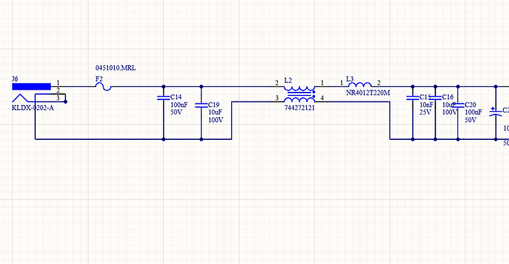
But the PCB layout shows a solid ground plane directly underneath the choke.
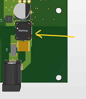
Imagine a GND plane below the chocke.
The intention is usually good: keep the ground plane continuous.Unfortunately, at high frequency, this decision often defeats the common-mode choke entirely.
The Hidden Assumption: Inductors Are Not Ideal
A common-mode choke is selected to present high impedance to common-mode currents, especially at high frequency.This assumes the choke behaves as an inductor over the frequency range of interest.
In reality, inductors are not ideal components.
Every inductor includes:
-
Winding-to-winding capacitance
-
Winding-to-core capacitance
-
Winding-to-PCB capacitance
As frequency increases, these parasitic capacitances become dominant. At a certain point — the self-resonant frequency — the inductive impedance stops increasing.
Above this frequency, the inductor no longer behaves inductively.
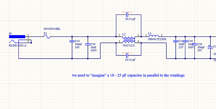
It behaves capacitively.
This behaviour is shown clearly in impedance-versus-frequency plots, where impedance peaks and then falls as frequency increases.

RED expert from Wurth is my favourite tools! we can see from theabove the effect of the parassitic winding capacitor.
What the Ground Plane Really Does
When a solid ground plane is placed under a common-mode choke, it creates an additional parasitic capacitance.
The choke winding and the ground plane form a parallel-plate capacitor.Even a small copper area can easily add tens of picofarads of capacitance.
This parasitic capacitance:
-
Appears in parallel with the choke
-
Lowers the self-resonant frequency
-
Creates a high-frequency bypass path
At high frequency, common-mode current now has an alternative route:
-
Through the parasitic capacitance
-
Into the ground plane
-
Back to the source
The current no longer needs to flow through the choke.

Why This Breaks the Common-Mode Filter
At low frequency, the choke still behaves as expected. At high frequency — where EMC problems usually occur — the situation changes.
Because:
-
The choke impedance collapses above self-resonance
-
The parasitic capacitive path has low impedance
The common-mode choke becomes progressively ineffective exactly where it should be most useful.
This is why many designs:
-
Look correct on paper
-
Pass low-frequency conducted tests
-
Fail radiated emissions above a few MHz
At high frequency, current follows lowest impedance, not schematic intent.
This Is Why the Schematic Does Not Reveal the Problem
The schematic shows:
-
A common-mode choke
-
A ground reference
What it does not show:
-
Parasitic capacitance to the ground plane
-
Self-resonant behaviour of the inductor
-
High-frequency displacement currents
As a result, this issue is:
-
Invisible in the schematic
-
Easy to miss during layout
-
Very obvious in the EMC chamber
Practical Layout Guidance
A simple rule that works well in practice:
Do not place solid reference planes directly under common-mode chokes.
Instead:
-
Clear copper underneath the choke
-
Or strictly control the copper area and distance
-
Especially on the layer directly below the component
This forces common-mode current to flow through the choke instead of bypassing it capacitively.
Final Thought
Common-mode chokes fail in real products not because they are wrongly chosen, but because their parasitic behaviour is unintentionally amplified by the PCB layout.
Understanding how inductors behave beyond their ideal model is essential for effective EMC design.
Written by Francesco Poderico
More on EMC
EMC
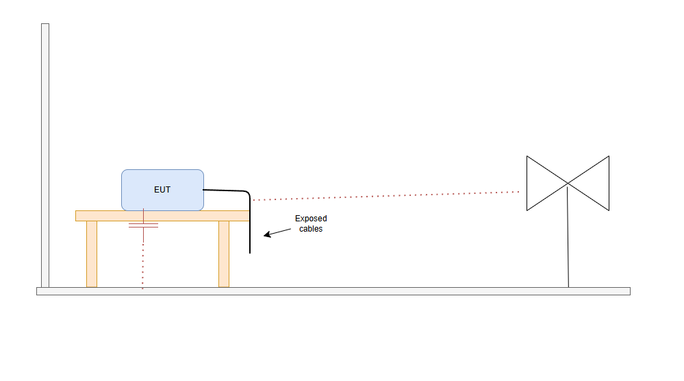
Why Moving the EUT Changes the Emissions Plot
1. Introduction – why a small change can make great differences in the plot Did this happen to you. You go to the testing lab. you do a full RE scan and the scan looks great. Then you - Rotate the EUT 90° - Lift a cable - Move the EUT by 20 cm - Change cable routing And the emissions plot change
Francesco Poderico · · 3 min read
EMC
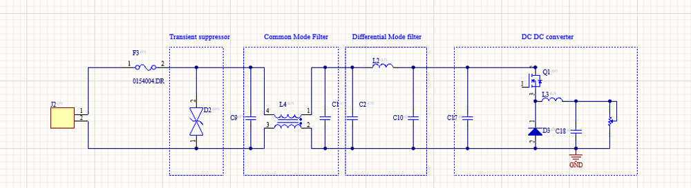
Power Supply Emissions: How I Separate Differential Mode from Common Mode
When I debug EMC problems on a DC/DC converter, I use a very simple test to understand whether the dominant mechanism is Differential Mode (DM) or Common Mode (CM). The test is simple: I increase the load and observe what happens to the emissions. If: - The peak frequencies stay the same,
Francesco Poderico · · 3 min read
EMC
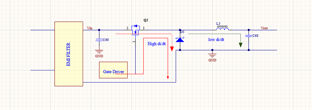
Identifying Low di/dt and High di/dt Currents in DC‑DC Converters
Introduction In switch‑mode DC‑DC converters, not all currents are equal from an EMC, signal integrity, or reliability perspective. A critical distinction must be made between low di/dt current paths and high di/dt current paths. Misidentifying these paths is one of the most common root c
Francesco Poderico · · 4 min read