
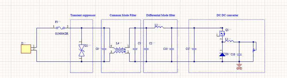
When I debug EMC problems on a DC/DC converter, I use a very simple test to understand whether the dominant mechanism is Differential Mode (DM) or Common Mode (CM).
The test is simple:
I increase the load and observe what happens to the emissions.
If:
-
The peak frequencies stay the same,
-
But the amplitude increases with load,
then the behaviour is consistent with differential-mode emissions.
This is aligned with what TI explains in their EMI material:
-
Differential-mode noise increases with load current.
-
Common-mode noise is largely independent of load current.
This gives us a very practical diagnostic tool.
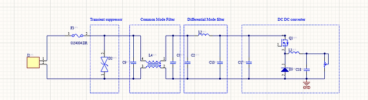
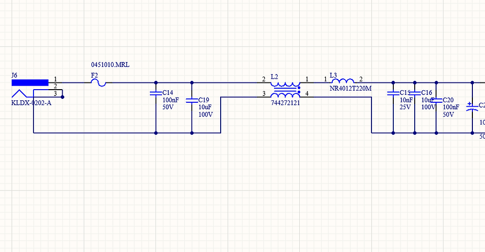
Typical input stage of a DC DC converter.
Understandinf Differential Mode and Common Mode emission
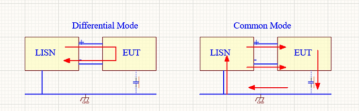
To understand why load affects DM more than CM, we must look at the current paths.
Differential Mode Path
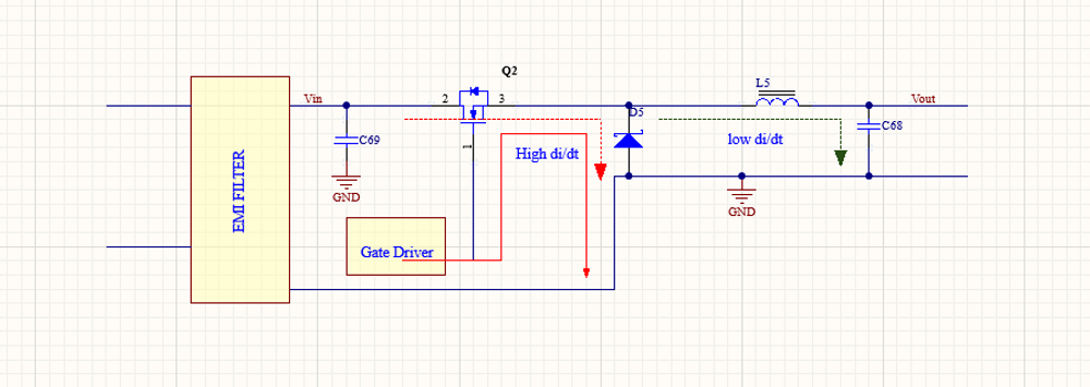
In differential mode, the noise current flows in the normal power loop:
LISN (+) → EUT → LISN (−)
The current flows between line and return.
The parasitic capacitance between the EUT and chamber ground does not significantly participate in this loop.
In a DC/DC converter:
-
The average inductor current equals the load current.
-
The input current is a pulsating waveform proportional to load.
So when load increases:
IOUT↑ ⇒ IDM ↑
Since the differential-mode noise is generated by this pulsating current, its amplitude increases with load.
The loop geometry does not change. The switching frequency does not change.Only the current magnitude increases.
Therefore:
-
Frequency peaks remain fixed.
-
Amplitude increases.
Common Mode Path
In common mode, the path is different.
The current flows:
Switch node → parasitic capacitance → chamber ground → LISN ground → back to the EUT
The parasitic capacitance between the EUT and the environment plays a key role.
Common-mode current is mainly driven by:
ICM=Cpar⋅dV/dt
Where:
-
Cpar is the parasitic capacitance to ground
-
dV/dt is the switching edge speed
In many fixed-frequency PWM converters:
-
dV/dt does not change significantly with load
-
Parasitic capacitanc e does not change
Therefore: ICM≈roughly constant with load
This is why common-mode emissions are often much less load-dependent.
A Practical EMC Debug Test
When failing conducted emissions (CE), I want direction.
Do I need:
-
A better common-mode choke?
-
Or a stronger differential (π) filter?
Here are two simple tests.
Test #1 – Move the Unit Closer to the Vertical Plane
most of the time the EUT is placed 40 cm from the vertical reference plane.
If I move the unit closer to the wall and emissions increase significantly, this suggests:
-
Strong coupling through parasitic capacitance
-
A common-mode contribution
This indicates that CM filtering may need attention.
Test #2 – Increase the Load
For example, increase load from 1 A to 2 A.
If emissions increase proportionally while peak frequencies remain fixed, this behaviour is consistent with differential-mode noise, because:
-
The DM loop is LISN (+) → EUT → LISN (−)
-
That current scales with load
In that case, improving the π filter or reducing hot-loop impedance is the correct direction.Why I have explain that?
During EMC debugging, many engineers guess:
-
“Maybe I need a bigger CM choke.”
-
“Maybe I need more capacitance.”
Instead of guessing, this simple test gives you the right direction.
If emissions scale with load → investigate differential mode.
If emissions do not scale with load → investigate common mode.
This is not a magic rule, and exceptions exist (burst mode, DCM transitions, variable frequency control), but for fixed-frequency PWM converters it is a very useful diagnostic tool.
Written by Francesco Poderico
More on EMC
EMC
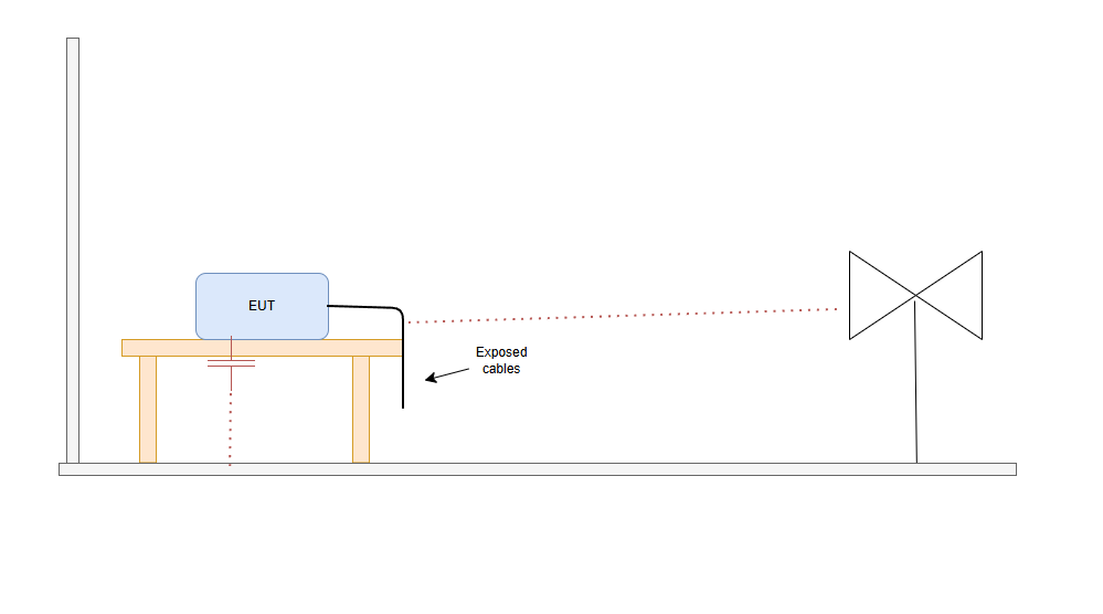
Why Moving the EUT Changes the Emissions Plot
1. Introduction – why a small change can make great differences in the plot Did this happen to you. You go to the testing lab. you do a full RE scan and the scan looks great. Then you - Rotate the EUT 90° - Lift a cable - Move the EUT by 20 cm - Change cable routing And the emissions plot change
Francesco Poderico · · 3 min read
EMC
Identifying Low di/dt and High di/dt Currents in DC‑DC Converters
Introduction In switch‑mode DC‑DC converters, not all currents are equal from an EMC, signal integrity, or reliability perspective. A critical distinction must be made between low di/dt current paths and high di/dt current paths. Misidentifying these paths is one of the most common root c
Francesco Poderico · · 4 min read
EMC
Why Placing a Ground Plane Under a Common-Mode Choke Often Makes EMI Worse
This is one of the most common layout mistakes I see during EMC reviews. The schematic is correct.The common-mode choke is correctly placed at the interface. But the PCB layout shows a solid ground plane directly underneath the choke. Imagine a GND plane below the chocke. The intention is usua
Francesco Poderico · · 3 min read