
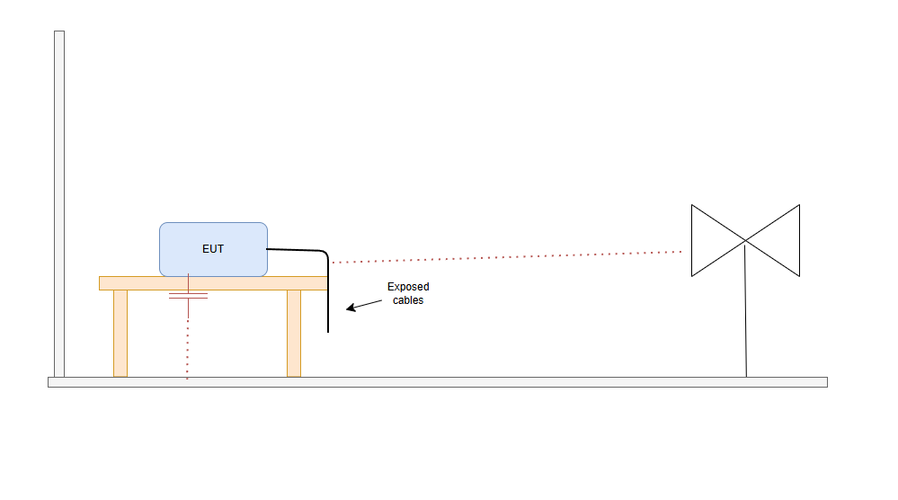
1. Introduction – why a small change can make great differences in the plot
Did this happen to you. You go to the testing lab. you do a full RE scan and the scan looks great. Then you
-
Rotate the EUT 90°
-
Lift a cable
-
Move the EUT by 20 cm
-
Change cable routing
And the emissions plot changes.
This is not randomness. It is physics.
Radiated EMC measurements are strongly influenced by how the product couples to its environment.I want to discuss this today, so, next time, when you are in a chambe and youmove a cable, or move the EUT, change a cable, etc. you can quickly identify the issue.
2. The Cable Is the Real Antenna
Most electronics products:
-
The PCB is small
-
The cables are long
Long conductors carrying common-mode current behave as antennas.
Why Common-Mode Current Radiates
Common-mode current flows:
-
In the same direction on all conductors
-
Returning through parasitic capacitance to ground
-
Using the chamber ground plane as a return path
Even a few milliamps of CM current at 30–200 MHz can radiate significantly.
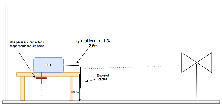
In a RE chamber the common mode path is artificially controlled by the test setup.
What Happens When You Move the Cable
Changing cable position changes:
-
Its effective antenna length
-
Its height above the ground plane
-
Its orientation relative to the measurement antenna
-
Its coupling to the EUT enclosure
The radiated field changes accordingly.
This is why lifting a cable off the table can increase emissions.
3. Height Above Ground Plane: Image Theory in Practice
In a semi-anechoic chamber:
-
The floor is conductive
-
The EUT sits on a table (typically 80 cm high)
The conductive floor creates an “image” of the cable (image theory do you remember we study this at the uni).
When you change:
-
EUT height (by adding a cardboard box under the EUT)
-
Cable droop
You change:
-
The effective antenna structure
-
The radiation pattern
-
The field strength at the measurement antenna
Small height changes can produce several dB variation.
So... by moving the EUT of ... say 10 cm "up" you have a emission reduction. then CM emission is happening.

4. Rotating the EUT: Polarization and Radiation Pattern
Rotating the EUT changes:
-
The orientation of the dominant radiating structure
-
The polarization of the field
-
The coupling between cable and antenna
Radiation is directional.
If the dominant current path is aligned with the antenna polarization, the measured level increases.
If it is orthogonal, it decreases.
This explains why:
-
0°, 90°, and 180° positions can show different peaks
-
Some frequencies are more sensitive than others
5. How to Interpret These Changes During Debugging
When emissions change after moving the EUT:
If rotating the product changes amplitude significantly:
The product has directional radiation (likely cable-driven).
If lifting the cable increases emissions:
Strong common-mode coupling to the ground plane.
If twisting the cable reduces emissions:
Radiation dominated by loop area.
If touching the enclosure changes emissions:
Poor enclosure bonding or floating metal parts.
Movement is a diagnostic tool — not a nuisance.
6. Practical Debug Strategy
During pre-scan:
-
Intentionally move cables
-
Rotate the EUT
-
Lift and drop cables
-
Lift the EUT
-
Change cable routing
If emissions are unstable:
-
You likely have common-mode current problems
-
Filtering or return path control needs improvement
A robust design shows limited sensitivity to cable position.
7. Conclusion
If your emissions plot changes when you move the EUT, it does not mean the test is unreliable.
It means:
-
The product is interacting with its environment.
-
Cables are radiating.
-
Common-mode current exists.
Understanding this allows you to use movement as a diagnostic method rather than treating it as noise in the measurement.
Written by Francesco Poderico
More on EMC
EMC
Power Supply Emissions: How I Separate Differential Mode from Common Mode
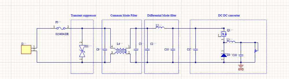
When I debug EMC problems on a DC/DC converter, I use a very simple test to understand whether the dominant mechanism is Differential Mode (DM) or Common Mode (CM). The test is simple: I increase the load and observe what happens to the emissions. If: - The peak frequencies stay the same,
Francesco Poderico · · 3 min read
EMC
Identifying Low di/dt and High di/dt Currents in DC‑DC Converters
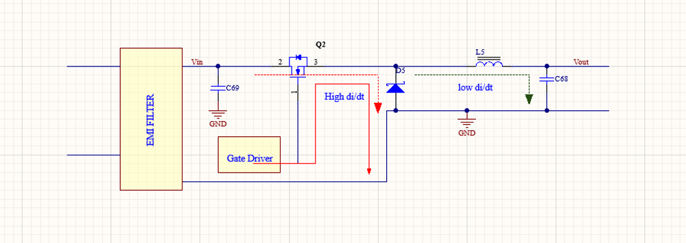
Introduction In switch‑mode DC‑DC converters, not all currents are equal from an EMC, signal integrity, or reliability perspective. A critical distinction must be made between low di/dt current paths and high di/dt current paths. Misidentifying these paths is one of the most common root c
Francesco Poderico · · 4 min read
EMC
Why Placing a Ground Plane Under a Common-Mode Choke Often Makes EMI Worse
This is one of the most common layout mistakes I see during EMC reviews. The schematic is correct.The common-mode choke is correctly placed at the interface. But the PCB layout shows a solid ground plane directly underneath the choke. Imagine a GND plane below the chocke. The intention is usua
Francesco Poderico · · 3 min read