
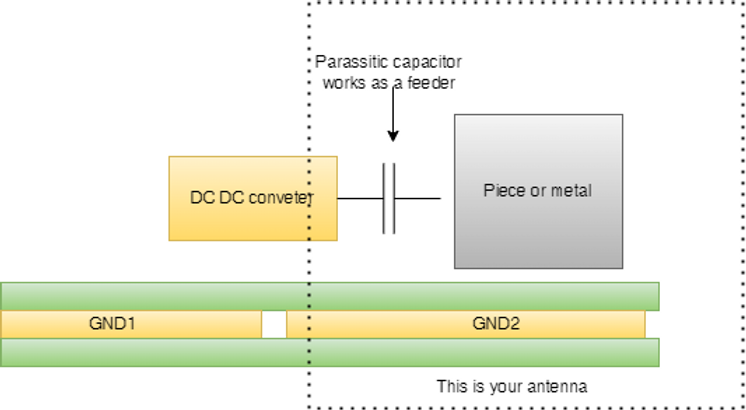
As I mentioned in two previous posts, I have discussed the emission path of an insulated DCDC converter below the frequency of 80 MHz.
It has been shown how a capacitor placed between the pins Vout- and Vin- can reduce the emissions from the DC-DC converter.
After that, we have analyzed the emission path in the range of 80 MHz to 250 MHz.
As well as reducing these emissions, we have also seen how to do so.
The next step in this discussion will be to examine the emission path in the range of 200 MHz - 1 GHz.
The best way to minimize will of course be discussed.
Analyzing the emission path between 200 MHz and 1GHz.
In Part 2, I discussed how to make an antenna with three components
-
A piece of metal (please notice it doesn't need to be a wire)
-
A feeder
-
A ground plane
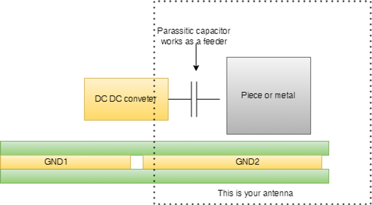
In point 1, I didn't say we needed a wire, I said we needed a piece of metal.
If your DC-DC converter uses a heat sink, for example. The heatsink itself will behave as if it were a patch antenna. Lastly, the feeder consists of either a MOS or a power transistor connected to the heatsink.
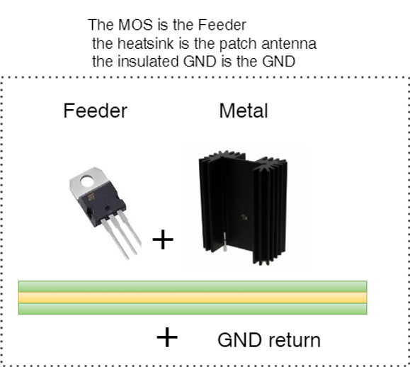
I would like to give you another example.
An electronic board is enclosed in a metal enclosure, and the enclosure is insulated from the DC-DC converter by the metal enclosure. In this case, the metal enclosure becomes your antennal and the feeder could be the parasitic capacitor between the DCDC converter and the enclosure itself in this case.

As a rule of thumb, in cases such as these, I have found that we will see emissions, normally above 200 MHz in my experience. Identifying the "antenna" is one of the most difficult parts of the process. Sometimes, it may be the heatsink, sometimes it may be the enclosure, and sometimes it may be the copper land on your PCB that needs to be repaired.
Once you have figured out what the "antenna" is. There is a need to "break" the structure in order to do this.
What are the steps we need to take in order to accomplish this? You can accomplish this by connecting the "antenna" to the Vout- of your DC to DC converter, as I explained previously.
Sometimes the connection is made in DC (by using an inductor or a 0 ohm link) while at other times it is made in AC, by using, for instance, a Y capacitor for example.
There is one thing I would like to remind you about, and it is that typically the value of the capacitor does not matter.
As soon as we break the antenna structure, the emission will cease to be presen!
I hope you enjoed it, see you next time!
Written by Francesco Poderico
More on EMC
EMC
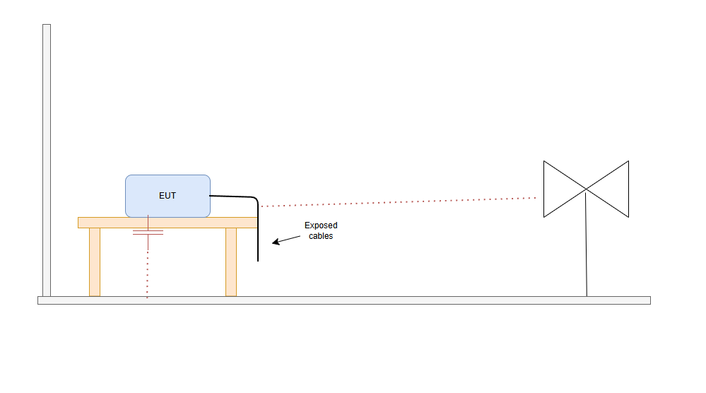
Why Moving the EUT Changes the Emissions Plot
1. Introduction – why a small change can make great differences in the plot Did this happen to you. You go to the testing lab. you do a full RE scan and the scan looks great. Then you - Rotate the EUT 90° - Lift a cable - Move the EUT by 20 cm - Change cable routing And the emissions plot change
Francesco Poderico · · 3 min read
EMC
Power Supply Emissions: How I Separate Differential Mode from Common Mode
When I debug EMC problems on a DC/DC converter, I use a very simple test to understand whether the dominant mechanism is Differential Mode (DM) or Common Mode (CM). The test is simple: I increase the load and observe what happens to the emissions. If: - The peak frequencies stay the same,
Francesco Poderico · · 3 min read
EMC
Identifying Low di/dt and High di/dt Currents in DC‑DC Converters
Introduction In switch‑mode DC‑DC converters, not all currents are equal from an EMC, signal integrity, or reliability perspective. A critical distinction must be made between low di/dt current paths and high di/dt current paths. Misidentifying these paths is one of the most common root c
Francesco Poderico · · 4 min read