
Quick Recap of Part 1
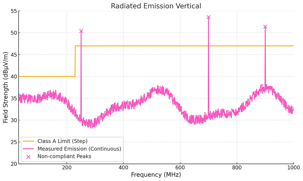
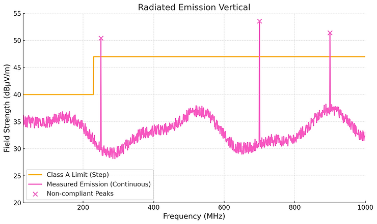
In Part 1, we explored how a simple change in antenna orientation can help you tell whether a radiated emission is coming from your PCB or from the attached cables .By running both vertical and horizontal measurements with the antenna at the same height (1 m above the ground), you can spot cable-related emissions quickly. If an emission changes significantly between vertical and horizontal, it’s a strong clue that the cable is acting as the radiator. This can save you from unnecessary PCB re-layouts and point you toward easier fixes, like cable ferrites or better routing.
The External Power Supply Factor
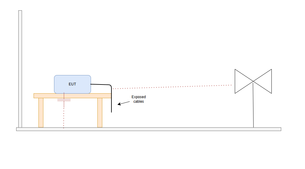
Many modern products use an external power supply — think wall warts, desktop bricks, or industrial adapters.When you test the complete system (EUT + external PSU), the radiated emissions are a combination of:
-
The noise generated by your product.
-
The noise generated by the external PSU.
-
The power supply's cable and the cable length, as explained in other post influence the total RE.
The Battery Substitution Technique
Here’s a practical way to separate the two contributions:
-
Baseline Measurement
-
Run a vertical RE test with the PSU connected.
-
Ask the EMC house to use this as baseline.
-
-
power your product with a Battery
-
Replace the PSU with a battery of the same voltage (e.g., if the PSU is 12 V, use a 12 V battery).
-
Keep the cable from the battery to the EUT as short as possible.
-
This eliminates switching noise from the PSU and removes its cable from the test.
-
-
Repeat the Test
-
Run the vertical RE measurement again under exactly the same conditions.
-
compare the 2 RE and check what is due to the power supply (plus power cord_ and what is due to your unit.
How to Interpret the Results
-
If the failing emissions disappear or drop well below the limit: The culprit is the PSU or the combination of PSU + EUT.
-
Try a different PSU of the same voltage and power rating.
-
Check the PSU cable for shielding and routing.
-
Consider adding common-mode filtering where the PSU enters your product.
-
add ferrites on the power cable
-
-
If the failing emissions remain essentially the same: The problem is inside your product.
- Now you can focus your debug time on PCB layout, grounding, and component-level fixes.
Wrapping Up
The battery substitution trick is quick, easy, and can often pinpoint the source of a 30 MHz–300 MHz failure in just a few minutes. It’s another example of how small, controlled changes to the EMC test setup can give you big insights into the problem.
Written by Francesco Poderico
More on EMC
EMC
Why Moving the EUT Changes the Emissions Plot
1. Introduction – why a small change can make great differences in the plot Did this happen to you. You go to the testing lab. you do a full RE scan and the scan looks great. Then you - Rotate the EUT 90° - Lift a cable - Move the EUT by 20 cm - Change cable routing And the emissions plot change
Francesco Poderico · · 3 min read
EMC
Power Supply Emissions: How I Separate Differential Mode from Common Mode
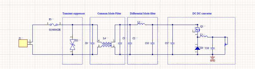
When I debug EMC problems on a DC/DC converter, I use a very simple test to understand whether the dominant mechanism is Differential Mode (DM) or Common Mode (CM). The test is simple: I increase the load and observe what happens to the emissions. If: - The peak frequencies stay the same,
Francesco Poderico · · 3 min read
EMC
Identifying Low di/dt and High di/dt Currents in DC‑DC Converters
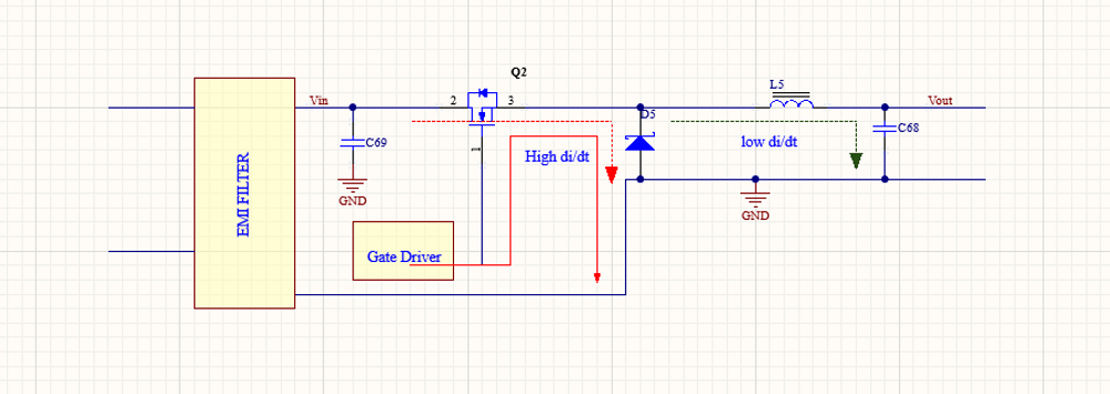
Introduction In switch‑mode DC‑DC converters, not all currents are equal from an EMC, signal integrity, or reliability perspective. A critical distinction must be made between low di/dt current paths and high di/dt current paths. Misidentifying these paths is one of the most common root c
Francesco Poderico · · 4 min read