
Back in the day, when testing was conducted for EMC, it was possible to perform tests, such as immunity tests, during which the device would degrade.
Let's say, for example, that you were performing an RF immunity test of a light controller, and during this test, the light flickered a little bit.
As far as the test is concerned, it may have been a success for some, such as the manufacturer, while for others (such as the testing house), it could be a failure because the light flashed during the test.
How do you feel about this? What are your thoughts? What was the result of the test above? Was it a failure or was it a pass?
Let's take a look at what's next...
The European Union (EN) standards are responsible for preventing such arguments during tests since they defined three levels of criteria in EN 61000-6-1 in 2007, which is the standard that applies to all European Union (EN) standards.
As a result, the EN has finally defined 3 criteria to stop the above arguments, and gradually, slowly, other nations have started to adopt the following criteria, with different degrees of implementation.
-
Criteria A is the strictest. According to these criteria, it is not acceptable for performance to degrade or functions to be lost.
-
Criteria B states that the equipment is intended to operate as intended after the test. After the test, the equipment will continue to operate as normal as long as it has not lost any performance or functionality.
-
Criteria C allows a temporary loss of function or functionality, provided that the equipment is able to self-recover, or that it is able to be restored by an operator over the internet if it is unable to do so on its own.
Conductive and radiated immunity must pass Criteria A! a few days ago I started to write a document called EMC cheatsheet. In that spreadsheet, you can see that on CI and RI we must pass Criteria A.
Good luck and happy testing!
Written by Francesco Poderico
More on EMC
EMC
Why Moving the EUT Changes the Emissions Plot
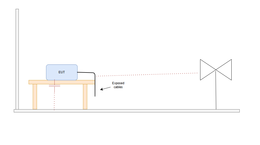
1. Introduction – why a small change can make great differences in the plot Did this happen to you. You go to the testing lab. you do a full RE scan and the scan looks great. Then you - Rotate the EUT 90° - Lift a cable - Move the EUT by 20 cm - Change cable routing And the emissions plot change
Francesco Poderico · · 3 min read
EMC
Power Supply Emissions: How I Separate Differential Mode from Common Mode
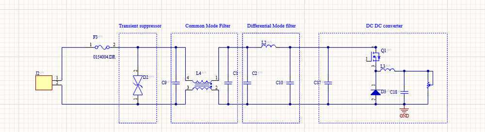
When I debug EMC problems on a DC/DC converter, I use a very simple test to understand whether the dominant mechanism is Differential Mode (DM) or Common Mode (CM). The test is simple: I increase the load and observe what happens to the emissions. If: - The peak frequencies stay the same,
Francesco Poderico · · 3 min read
EMC
Identifying Low di/dt and High di/dt Currents in DC‑DC Converters
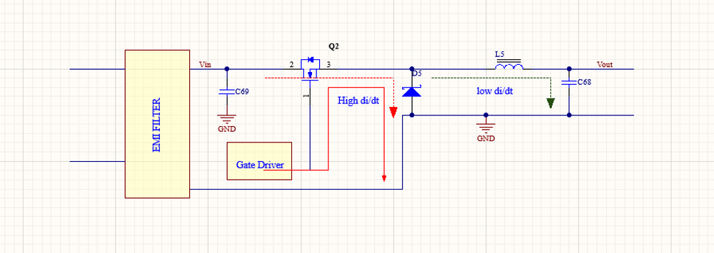
Introduction In switch‑mode DC‑DC converters, not all currents are equal from an EMC, signal integrity, or reliability perspective. A critical distinction must be made between low di/dt current paths and high di/dt current paths. Misidentifying these paths is one of the most common root c
Francesco Poderico · · 4 min read