
How This Article Started
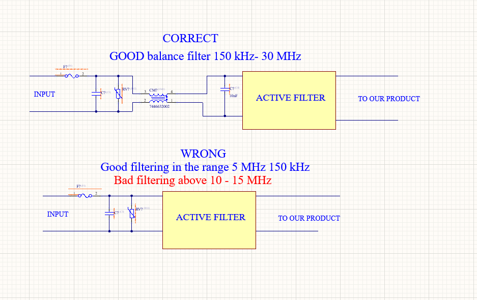
I was reviewing a design for a customer a while back, and they had this active capacitor circuit being used as an EMI filter. My customer looked at the schematic and asked me, "Francesco, what is this?"
I couldn't help myself – I smiled and said, "That's a 1 Farad capacitor."
We both had a good laugh. But that moment stuck with me, because it's actually a perfect way to understand what active EMI filters do. They can behave like impossibly large passive components, without actually being large at all.
So let's talk about them.
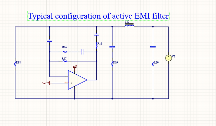
The above is a typical configuration of an active EMI filter.
You know that feeling when you're deep into a project, EMC testing is around the corner, and your conducted emissions look terrible below a few MHz? You keep adding bigger ferrites, stacking more capacitors, and it still feels like you're just throwing parts at the problem.
This is usually when someone mentions active EMI filters. They're not some magical solution, and they definitely don't replace doing good EMC design from the start. But when passive filtering starts hitting a wall, they can actually work really well.
This article is a straightforward, practical look at active EMI filters, inspired by a Texas Instruments app note called "Using an Active EMI Filter in Power Converters". I'm skipping the equations for now – just focusing on how they actually work and when you'd want to use them.
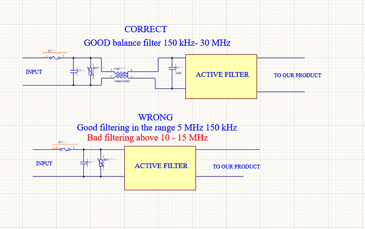
Above we can see an example of good Active filtering strategy vs bad strategy.
Why Passive Filters Sometimes Aren't Enough
Traditional EMI filtering is pretty straightforward:
-
Inductors and common-mode chokes
-
Capacitors to ground or between lines
-
Ferrites and damping networks
This stuff works great at higher frequencies. But you start running into problems when:
-
Most of your noise sits at low frequencies (like right around that 150 kHz limit)
-
Your load current varies a lot
-
The inductors you need are getting huge and expensive
-
Your filter behaves differently than expected because of source and load impedances
In real switch-mode power supplies, the worst emissions often show up right at the bottom of the frequency band – exactly where passive components are least effective.
How Active EMI Filters Actually Work
Here's the thing: active EMI filters don't block noise the traditional way.
Instead, they:
-
Sense the noise (usually current or voltage)
-
Generate a signal that opposes it
-
Inject that opposing signal back into the line
It's basically noise cancellation instead of just blocking. Pretty clever, right?
The key insight from the TI paper is that an active circuit can act like a really large capacitor or inductor, without actually being physically large.
The "Active Capacitor" Concept (Or My "1 Farad Capacitor" Joke)
Remember my story from the beginning? That's exactly what's happening here.
One of the easiest ways to understand these filters is thinking about them as "active capacitors."
Rather than using a massive physical capacitor to shunt noise to ground:
-
The circuit senses the noise voltage
-
An amplifier pushes current proportional to that noise
-
From the noise source's perspective, it looks like there's a much bigger capacitor there
To the outside world, your power converter appears to have much lower noise impedance, even though you're using small components. It's like having that "1 Farad capacitor" I joked about – except it's real, just implemented differently.
This is especially useful at low frequencies where real capacitors would need to be ridiculously large.
Where It Fits in Your Design
Te active filter isn't a standalone solution. You must use in conjunction with a passive filter
In practice, you'll have:
-
A basic passive filter (still needed for safety and high-frequency noise)
-
The active filter targeting low-frequency conducted emissions
-
Both working together
Think of it as: passive filtering handles the high end of the band, active filtering tackles the low end.
When Active Filters Make Sense
-
Failing conducted emissions around 150 kHz
-
Power supplies with highly variable loads
-
Designs where the inductors are already too big
-
Applications where size and weight really matter
You'll find them in:
-
Industrial power supplies
-
Automotive DC-DC converters
-
Medical equipment
Active + Passive: The Real-World Approach
In actual products, the best approach is almost always combining both:
-
Start with good layout and grounding (always!)
-
Add a minimal passive EMI filter
-
Use an active filter to knock down low-frequency noise
-
Fine-tune with small passive components
You're not aiming for zero EMI – you're aiming for smaller magnetics, fewer ferrites, and better margin at the low end of the frequency band.
Bottom Line
Active EMI filters aren't some experimental tech anymore – but they are advanced tools.
If you use them to avoid doing proper EMC design, you're going to have a bad time. But if you use them to extend what passive filtering can do, they can be incredibly effective.
In the next article, I'll cover:
-
Block diagrams showing how they actually work
-
Practical implementation tips
-
A simple decision checklist
Reference: Texas Instruments – Using an Active EMI Filter in Power Converters (SLYP833)
If your product has failed EMC testing and you are stuck, you can email me with:
• Product type (industrial / consumer / medical)
• Test that failed (RE, CE, RI, ESD, etc.)
• Frequency range of the issue (if known)
• Main power voltages involved (if known)
I will tell you whether this is something I typically help with and where the problem usually comes from.
Written by Francesco Poderico
More on EMC
EMC
Why Moving the EUT Changes the Emissions Plot
1. Introduction – why a small change can make great differences in the plot Did this happen to you. You go to the testing lab. you do a full RE scan and the scan looks great. Then you - Rotate the EUT 90° - Lift a cable - Move the EUT by 20 cm - Change cable routing And the emissions plot change
Francesco Poderico · · 3 min read
EMC
Power Supply Emissions: How I Separate Differential Mode from Common Mode
When I debug EMC problems on a DC/DC converter, I use a very simple test to understand whether the dominant mechanism is Differential Mode (DM) or Common Mode (CM). The test is simple: I increase the load and observe what happens to the emissions. If: - The peak frequencies stay the same,
Francesco Poderico · · 3 min read
EMC
Identifying Low di/dt and High di/dt Currents in DC‑DC Converters
Introduction In switch‑mode DC‑DC converters, not all currents are equal from an EMC, signal integrity, or reliability perspective. A critical distinction must be made between low di/dt current paths and high di/dt current paths. Misidentifying these paths is one of the most common root c
Francesco Poderico · · 4 min read