
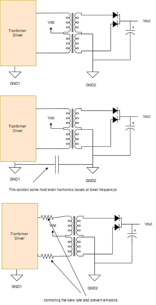
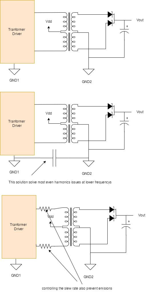
I visited Scotland on holiday, a beautiful country! There is so much history in Edinburgh, and I also enjoyed visiting Glasgow. It is difficult for a consultant engineer to stop working entirely, as you can imagine. I received a call from an IT company that already has a product on the market, and they made some changes due to chip shortages, and guess what? They had problems with EMC. As a result, I asked them what the problem was, and I tried to point them in the right direction.Now since this issue is quite difficult to solve, if you don't know the reason, I decided to write a small post to direct you to solve this kind of issue.Imagine designing your own insulated DCDC converter. As a standard configuration, you have a transformer driver, an insulation transformer, and a rectifier. Here is my drawing.Can such a small circuit cause any problems?You may encounter the following issues:Excessive conductive emissionsRadiated emissions can sometimes occur
Whenever you observe harmonic multiples of a transformer driver's oscillation frequency during a CE test, note them down and determine if they are odd or even.Adding a Y capacitor between the "input" GND and the "output" GND usually cures even harmonics. I suggest leaving some physical space for a Y capacitor, maybe start the test without it and then fit it if you fail the CE test. This capacitor's value is difficult to predict until you perform the test, so I suggest leaving some physical room for it.In a previous post, I explained how this capacitor works.How about the odd harmonics?It is likely that you are emitting above 30 MHz if you see odd harmonics.We have odd harmonics because the rising edge is too fast, so don't panic.The solution is simple, reduce the rise time of your transformer driver. Adding a small resistor in series between the transformer driver and the transformer or using a transformer driver with slew rate control can accomplish this. This is what I would suggest (this is what I would suggest).Is there anything else we can do?There are still two issues to resolve.I1. SRF is the resonance frequency of every transformer. It is possible to get higher voltage and higher emission if you drive the transformer at a frequency very close to this SRF. Therefore, be careful.I2. Overdrive and saturation have occurred in the transformer. In this case, a small resistor may be able to solve any problems that may occur; a small resistor between the driver and the transformer may help solve the problem.
Written by Francesco Poderico
More on Electronics
Electronics
How Parasitic Capacitance Breaks Optocoupler Isolation in Switching Power Supplies
Optocouplers are widely used in isolated power supplies to transfer feedback information across an isolation barrier. In schematics, they appear as a clean and robust solution: no galvanic connection, clear separation between primary and secondary, and good noise immunity. In practice, optocouplers
Francesco Poderico · · 3 min read
Electronics
Estimating the Lifetime of a Varistor on the Mains – What an Electronic consultant should know!
Introduction Varistors (typically MOVs) are widely used on mains lines for surge / transient protection. Under normal conditions they are passive, but when high‐voltage transients (switching surges, lightning induced, line overvoltage) occur, the varistor conducts, clamps the voltage and absorb
Francesco Poderico · · 2 min read
Electronics
Conductive Emissions due to lack of Bulk Capacitors
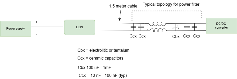
In one of my previous blogs, I discussed the importance of adding common mode filtering to power cables. Nevertheless, even the best filtering may not be enough to pass CE. When this occurs, most EMC testing houses recommend using "low frequency" ferrites, like Fair-Rite's excellent Material 31, whi
Francesco Poderico · · 3 min read