
In one of my previous blogs, I discussed the importance of adding common mode filtering to power cables. Nevertheless, even the best filtering may not be enough to pass CE. When this occurs, most EMC testing houses recommend using "low frequency" ferrites, like Fair-Rite's excellent Material 31, which in some cases may solve the problem.
My post will discuss a typical design mistake that creates CE issues at very low frequencies (below 30 MHz) that may not be resolved by using ferrites with Material 31 cores.
As a first observation, you should refrain from using ferrite for CE on power cables. There are several reasons for this. First and foremost, if you have, let us say, a 4A input, adding some ferrite will impact price, dimensions, and heat dissipation.
That's right, I said heat dissipation!
Now let's look at a typical mistake that I have seen in the last few years.
The lack of bulk capacitors
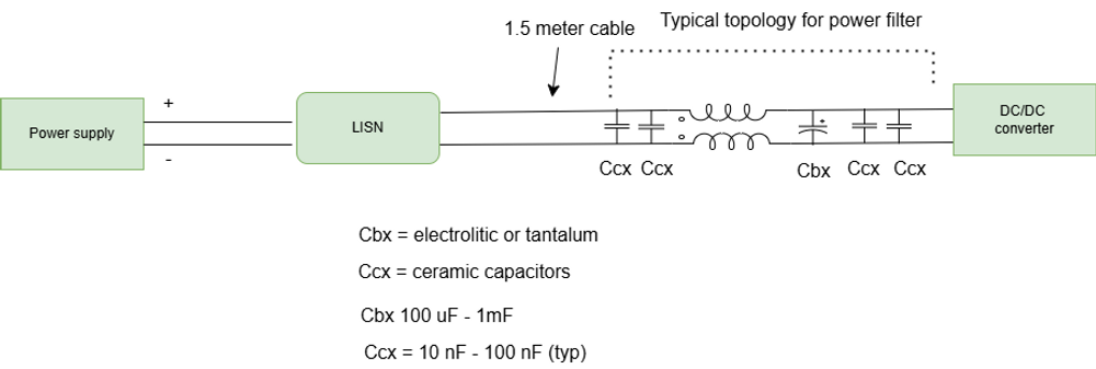
In order to begin our analysis, let's consider a DCDC converter's typical CM filter topology:
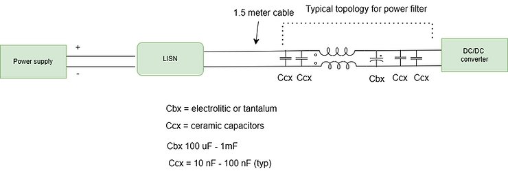
Figure 1. typical topology for input filter on a power supply
Each DCDC converter power supply should follow the above topology. As an example, we have a common mode choke whose insertion loss is -30 dB, some ceramic capacitors designed to minimize differential mode issues above 1 MHz, and a bulk capacitor designed to stabilize voltage below 200 KHz.
Now imagine that even with a common mode filter with an insertion loss of -30 dB, we still fail CE.
What could be the problem? (I'm talking about emission below 30 MHz).
For us to understand what the problem might be, we must understand how power moves from the power supply to the Cbx and Ccx capacitors and from the capacitors to the DC/DC converter.
So let's start considering the current loop from the Cbx and Ccx capacitors and the DC DC converter.
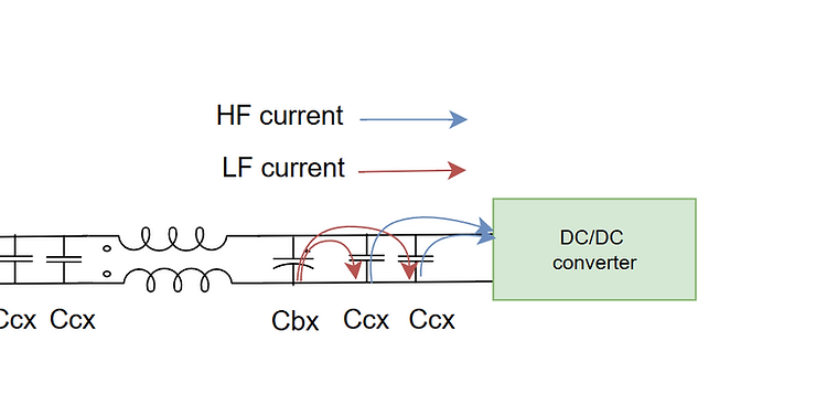
A DCDC converter is very demanding when it comes to "asking" current at high frequencies. Only ceramic capacitors fitted near the DC DC converter can provide this current.
Here is the blue current path.
Since ceramic capacitors are giving current to the DCDC converter, they require more charge, otherwise their voltage will decrease.
Ideally, the bulk capacitor (typically aluminium or tantalum) would provide this current. This current is shown in red.
Whenever the Cbx capacitor is large enough to supply that amount of current continuously to the Ccx capacitors, the above situation occurs.
Now let's analyze what happens when Cbx is too small.

If Cbx is too small, then there will be a drop in voltage across Cbx, and the power supply will be the next current source. You can see the yellow arrow.
Unfortunately, the high frequency current from the power supply crosses the LISN, which means that we will start seeing high frequency emissions from the spectrum analyzer connected to the LISN. Due to the fact that this emission is caused by differential mode currents, a common mode chocke can be inefficient in this regard.
Increasing Cbx is enough to fix this problem.
How can you check the value of Cbx before EMC ?
Here's a simple way to do it.
Connect the power supply to your equipment with a cable of 3-5 meters. With an oscilloscope, check that the ripple at the input of your power supply is less than 50 mV.
If it isn't, increase the Cbx or even the Ccx capacitor until you achieve the ripple you want.
Most of the time, a ripple of 100 mV causes problems during EMC testing.
I hope you enjoyed and will keep an eye on your Bulk capacitor.
Written by Francesco Poderico
More on Electronics
Electronics
How Parasitic Capacitance Breaks Optocoupler Isolation in Switching Power Supplies
Optocouplers are widely used in isolated power supplies to transfer feedback information across an isolation barrier. In schematics, they appear as a clean and robust solution: no galvanic connection, clear separation between primary and secondary, and good noise immunity. In practice, optocouplers
Francesco Poderico · · 3 min read
Electronics
Estimating the Lifetime of a Varistor on the Mains – What an Electronic consultant should know!
Introduction Varistors (typically MOVs) are widely used on mains lines for surge / transient protection. Under normal conditions they are passive, but when high‐voltage transients (switching surges, lightning induced, line overvoltage) occur, the varistor conducts, clamps the voltage and absorb
Francesco Poderico · · 2 min read
Electronics
Conductive emissions issues due to rectifier diodes
There is a feeling in me that sometimes the old books are better than the new ones. As an example, a book by Hnatek called Design of Solid State Power Supplies might be one of those gems that shouldn't be missed in your library if you are interested in solid-state power supplies. This old book s
Francesco Poderico · · 3 min read