
The analysis I do when designing a DCDC converter. (Part 1)
Francesco Poderico · · 2 min read
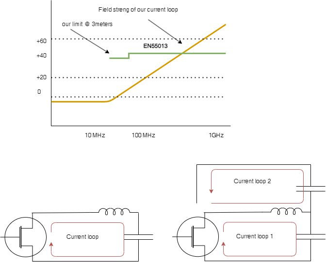
When we design electronics, there are a few things we shouldn't skip. Often, CEOs and CTOs pressure us to design things quickly. But what is the cheapest option? Should we spend one or two extra days analyzing the board or should we run it a second time?
My goal today is to discuss some design analysis I perform during the layout of a DCDC converter. These are general considerations that can be applied to all designs, not just DCDC converters. EMC appears to be failing primarily due to a lack of current loops that were overlooked by the designer. In this post, I will explain the design considerations I make to maximize my chances of passing EMC on the first try.
First of all, what is the estimated amount of radiation released by a looped current?
In any book on electromagnetic compatibility (EMC), we are going to find the formula relating the electric field strength of a loop antenna. :
E(x) = 13.2 * (10^-15) *(f^2) *A *I/x
A = area of the loop
I = current
x = distance from the loop
It is true that most books stop here, but most of them should go ahead of this discussion and explain how these concepts relate to the pass/fail in the real-world context.
Therefore, I use a spreadsheet with my limits (which I receive from the testing house), and then I estimate the electric field at a distance of 3 meters using the spreadsheet.
As a result, I end up with a graph that looks like the one I have just made in the drawings, and I am very pleased with it.
In most cases, estimating the current I is a difficult task; however, we have tools like LTSpice, spice 3f5, etc., and so we should not have any problem assessing the RMS value for the current using those tools.
In the process of performing this analysis, I sometimes discover that I am unable to pass the EMC test. Then what is the best thing for me to do?
We have a lot of options at our disposal. It is easiest to use capacitors in antiparallel, which is the simplest solution.
This is the kind of case wherein I create a second current loop that runs in a 180-degree phase with the first loop that will tend to eliminate the problem. In order to achieve this, it is easiest to place a capacitor "antiparallel" to the main capacitor, and this, in turn, will create a current loop that will tend to create a magnetic field in opposition to the first magnetic field that was created.
I hope you enjoyed it.
Bye now!
Written by Francesco Poderico
More on Electronics
Electronics
How Parasitic Capacitance Breaks Optocoupler Isolation in Switching Power Supplies
Optocouplers are widely used in isolated power supplies to transfer feedback information across an isolation barrier. In schematics, they appear as a clean and robust solution: no galvanic connection, clear separation between primary and secondary, and good noise immunity. In practice, optocouplers
Francesco Poderico · · 3 min read
Electronics
Estimating the Lifetime of a Varistor on the Mains – What an Electronic consultant should know!
Introduction Varistors (typically MOVs) are widely used on mains lines for surge / transient protection. Under normal conditions they are passive, but when high‐voltage transients (switching surges, lightning induced, line overvoltage) occur, the varistor conducts, clamps the voltage and absorb
Francesco Poderico · · 2 min read
Electronics
Conductive Emissions due to lack of Bulk Capacitors
In one of my previous blogs, I discussed the importance of adding common mode filtering to power cables. Nevertheless, even the best filtering may not be enough to pass CE. When this occurs, most EMC testing houses recommend using "low frequency" ferrites, like Fair-Rite's excellent Material 31, whi
Francesco Poderico · · 3 min read