
Some analysis I do when I design a DCDC converter. (Part 3)
Francesco Poderico · · 3 min read
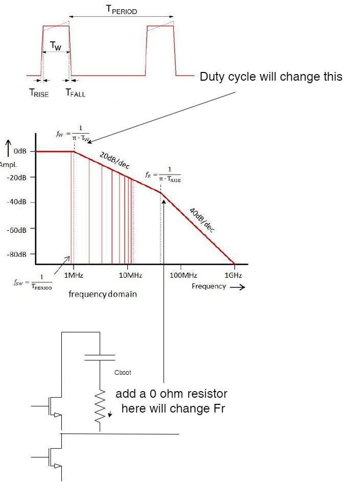
In the process of creating a new product from scratch, I always add components that I may not need in production when I am designing it. As an example, it does not cost anything to add an 0-ohm link or a "does not fit" capacitor in a critical spot where we think we might need them in the future (in case we have EMC issues in the future). This article is about a simple and straightforward design technique you can use to reduce the emissions of boost converters in the range of 30 MHz to 300 MHz by using a small and straightforward design technique.In this lesson, we will learn:What are the effects of the duty cycle of a DCDC converter on the emissions (for our example, this is 30 MHz)?In our example, we are going to look at how to reduce the total emission bandwidth (this is the 300 MHz in our example).The first part of this article will discuss why do we discuss the 30 MHz - 300 MHz frequency ran
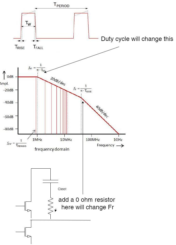
ge? There's no substitute for experience... oh, and math as well!If you want to be a true EMC expert, you need to be able to see any waveform in the frequency domain and understand its harmonics over all the frequencies.Let's take a look at the drawing I have made as an example. Imagine a switching DCDC converter with a Tw (window time) of 300 nsec and a rise time (fall time) of just 10 nsec, where the switching frequency is 800 kHz.There is a high probability that the majority of emission, in this case, will occur between 50 MHz and 300 MHz, which is to be expected. where fw=50 MHz is approximately equal to fw = 1/(pi*Tw) and fr = 1/(pi*Tr) There is an envelope of -20dB/dec between the emission spectrum between fw and fr. The emission envelope above fr is, on the other hand, -40 dB/dec above fr.By understanding this, we will be able to start to perform some "magic" in the field of emission once we know all of this.If, for example, we fail at the "lower end" of the frequency range (around 50 MHz) and all the standard techniques, such as bypassing, bulk capacitors, and antiparallel capacitors are not working, then that would be cause for concern. As a result, we will be able to play around with the duty cycle. Take a look at the drawing below. Can you tell me what happens when Tw is widened? When it is smaller, what happens to it? And what happens if it is larger?
YES we change fw, we can reduce just enough to pass the emission test.What should be done during the EMC testing? It is essential that you attend this event! to have control of the setup and change the input voltage! (you may need to reduce the input voltage range, but at least you can sell your product).What about Fw? How do we change?The rise time of a Boost converter depends on the quality of the Cboot. LESR capacitors are usually used as Cboots. Add a series resistor to the Cboot if you're willing to lose a small percentage of efficiency.tage of efficiency.The 0-ohm link is usually added in series to Cboot in all my designs. By adding a 1-10 ohm resistor, I can improve the emission if I encounter issues during EMC testing. The technique is straightforward and practical at the same time.
Written by Francesco Poderico
More on Electronics
Electronics
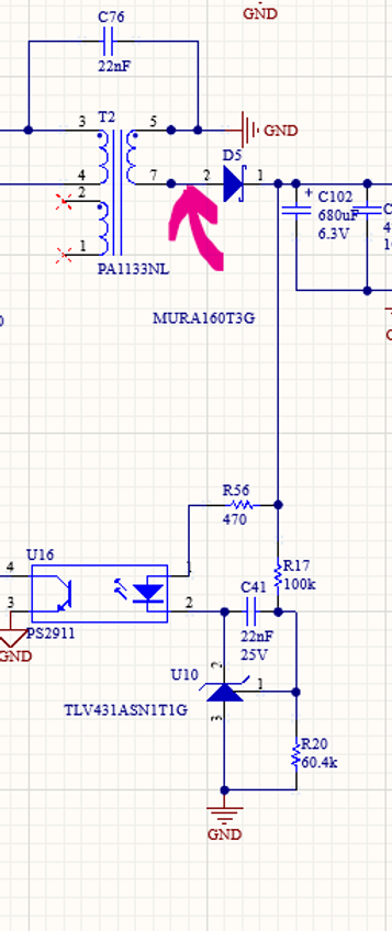
How Parasitic Capacitance Breaks Optocoupler Isolation in Switching Power Supplies
Optocouplers are widely used in isolated power supplies to transfer feedback information across an isolation barrier. In schematics, they appear as a clean and robust solution: no galvanic connection, clear separation between primary and secondary, and good noise immunity. In practice, optocouplers
Francesco Poderico · · 3 min read
Electronics
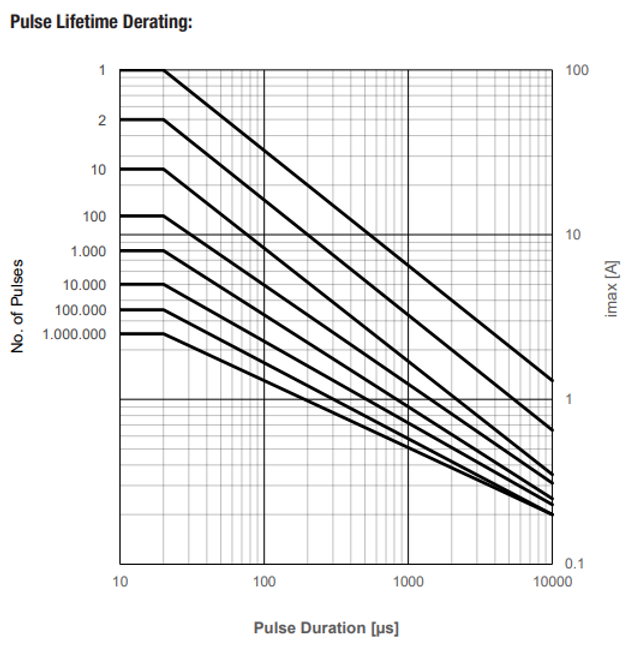
Estimating the Lifetime of a Varistor on the Mains – What an Electronic consultant should know!
Introduction Varistors (typically MOVs) are widely used on mains lines for surge / transient protection. Under normal conditions they are passive, but when high‐voltage transients (switching surges, lightning induced, line overvoltage) occur, the varistor conducts, clamps the voltage and absorb
Francesco Poderico · · 2 min read
Electronics
Conductive Emissions due to lack of Bulk Capacitors
In one of my previous blogs, I discussed the importance of adding common mode filtering to power cables. Nevertheless, even the best filtering may not be enough to pass CE. When this occurs, most EMC testing houses recommend using "low frequency" ferrites, like Fair-Rite's excellent Material 31, whi
Francesco Poderico · · 3 min read