
Mixed designs with ADC and DAC require some precautions.
Francesco Poderico · · 3 min read
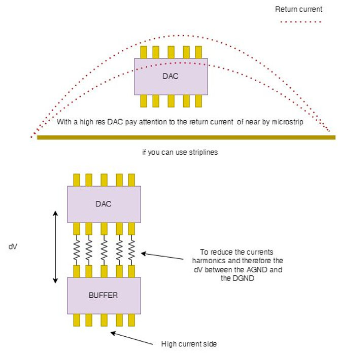
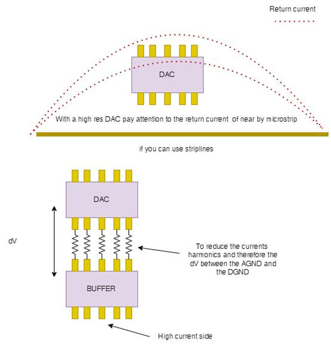
A few years ago, I worked on digital radio for a customer. It was a very complex design, but the reward for an electronic engineer such as me was enormous. It was a pleasure to work on every single part of the design. As I recall, I bought a few books to ensure that I was doing a good job, and the best book that I purchased at the time was titled "Grounds for Grounding" by Wiley, which I highly recommend, in particular chapter 9, which was the most useful chapter for me. The book is extremely well written, and it goes into great detail about how to connect a noisy digital ground with a clean analog ground of a device such as an ADC or DAC using a few different methods. It explains why they are called AGND and DGND on a datasheet and why they should be placed on the same plane on a datasheet.The guide also explains how to minimize the amount of noise between them and so on. In spite of that, that book did not explain to me what a "noisy" ground is, and what a "clear" ground looks like. As a result, I am sharing this with you at this time.There is no problem in getting 50 - 100 mV of 'ground noise' when we design a pure digital board. From the perspective of most designs, it is tolerable. What if we have an 8-bit DAC (or ADC) instead of a 16-bit DAC (or ADC)? Is it possible to tolerate a ground bounce of 50 mV?Assume for the time being that we will be using 1V as a voltage reference for our DAC. In that case, with an 8 bit DAC the resolution is 1V/256 = 3.9 mV.Similarly, we can build a table like this8 bit -> 3.9 mV -> 48 dB 16 bit -> 15 uV -> 96 dB18 bit -> 4 uV -> 108 dBetc.So in conclusion, we can say that despite the fact that we have an 8-bit DAC, we still need to be very careful. In the case of the above design, after spending a sleepless night studying the above book on how to best connect the "AGND" to the "DGND", we made the decision to use a single GND plane as the best way to connect the two. However, even though I was terrified of being able to use microstrips on a PCB, there was no choice since the PCB stack had been decided by others months earlier. As a result, I had to ask myself the following question:Can I know how much of an impact I will have on the "AGND" if I have a microstrip near my DAC? Due to the fact that I was looking for a noise insulation of about 80 decibels, this is a very important question to ask.Having said that, it is now time to return to the theory, and I made another table this time, with the dimensions of the strip lines in the vicinity of the DAC in mind.w/h = 1 -> 24 dB current reduction at a distance of 5ww/h = 5 -> 78 dB current reduction at a distance of 5wetc.It became clear to me that with the stack-up I had, I would never be able to achieve the dynamic insulation I wanted, and since I was not able to use strip lines and asymmetric strip lines, I was going to be in trouble. I decided to add a low pass filter to the distance of the DAC as well as a digital buffer so that the noise between the two GNDs could be minimized. As you can see in the drawing above, the resistor is the only component you will see; however, you can imagine an 18pF capacitor close to the DAC to complete the circuit.As far as I am concerned, it worked perfectly.If you do not wish to buy the book mentioned above, I recommend you take a look at AN from Analogue Devices. It will make you grow as an engineer, at least I did. There are a lot of good suggestions to be found in them.I hope you enjoyed it!
Written by Francesco Poderico
More on Electronics
Electronics
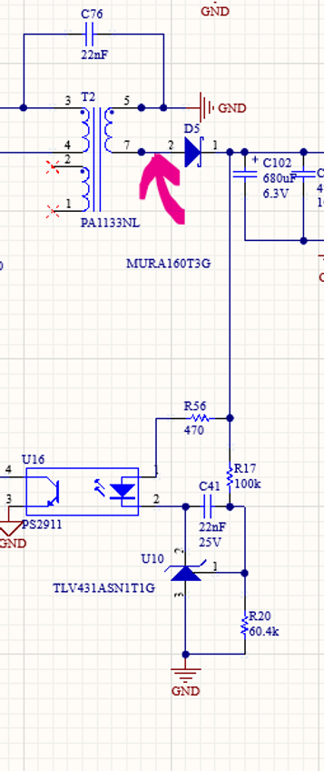
How Parasitic Capacitance Breaks Optocoupler Isolation in Switching Power Supplies
Optocouplers are widely used in isolated power supplies to transfer feedback information across an isolation barrier. In schematics, they appear as a clean and robust solution: no galvanic connection, clear separation between primary and secondary, and good noise immunity. In practice, optocouplers
Francesco Poderico · · 3 min read
Electronics
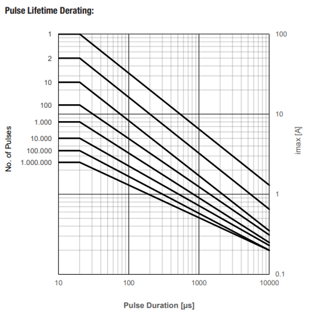
Estimating the Lifetime of a Varistor on the Mains – What an Electronic consultant should know!
Introduction Varistors (typically MOVs) are widely used on mains lines for surge / transient protection. Under normal conditions they are passive, but when high‐voltage transients (switching surges, lightning induced, line overvoltage) occur, the varistor conducts, clamps the voltage and absorb
Francesco Poderico · · 2 min read
Electronics
Conductive Emissions due to lack of Bulk Capacitors
In one of my previous blogs, I discussed the importance of adding common mode filtering to power cables. Nevertheless, even the best filtering may not be enough to pass CE. When this occurs, most EMC testing houses recommend using "low frequency" ferrites, like Fair-Rite's excellent Material 31, whi
Francesco Poderico · · 3 min read