
Have you ever seen corrosion on the solder joints on an old PCB? Or on the aluminium side of a power supply? Why we do have corrosion, and how can we stop it?
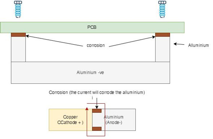
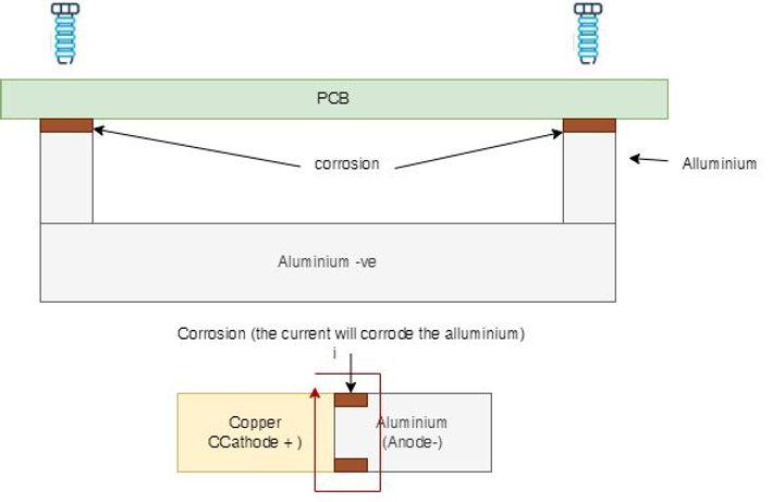
Every time we connect different metals with different Fermi levels, the chances are you have created a diode. Zener diodes work just based on this principle. Under proper environmental conditions (e.g. high humidity, water or salt), we may have an electrochemical reaction that will corrode the "Anode". For example, on a joint Aluminium Copper, the Aluminium will rust. The rust will happen in a place where some water may condensate. Without water, this process can't start. In the attached drawing, I have shown how something we do all the time can go wrong. Imagine we are using a PCB connected to ab aluminium base, and we use steel screws (same anodic voltage as copper) to join the PCB (copper) to the aluminium plate. If we have condensation in the proximity of copper/aluminium, then there will be some corrosion around that joint. I'm sure we have all seen this before.
If you google "Galvanic corrosion", you will find tables and a spreadsheet with the anodic voltage of many metals and materials. I suggest choosing the materials with the closest anodic voltages as much as possible to avoid surprises.
For Harsh environments (outdoor, high humidity/salt), I use material with less than 0.15V difference only! And if I can't, I mitigate the corrosion with conformal coatings, insulating, plating, etc.
For normal use (home appliance), I set 0.25V in my designs.
So, in the future, when you bolt your aluminium enclosure to your PCB, I'm sure you will do some research first, and you'll ask the right questions to your customer.
Have you had this issue before? please share your experience with us.
Bye now!
Written by Francesco Poderico
More on PCB
PCB
EMC Troubleshooting Part 3 — Broadband Footprints: 2‑Layer Boards & Plane Slots
Scope: Why some products show broadband radiated emissions from 30 MHz–1 GHz, why issues often persist up to 400 MHz–1 GHz even on multilayer boards, and how to prove and fix the root cause fast. 1) What “broadband” really means in RE On the plot, broadband looks like a wide hum
Francesco Poderico · · 4 min read

PCB
High-Speed Vias: Why Solid Ties Beat Thermal Reliefs
Thermal-relief “spokes” help solderability, but they add inductance and cut slots in your reference plane—exactly where high-frequency return current needs a short, wide path. For HDMI, PCIe, and other multi-GHz links, prefer solid connections to ground on anything that carr
Francesco Poderico · · 2 min read

PCB
Conductive Immunity failure due to a two layers stack PCB
Over the last ten years, I have seen so many PCBs fail conductive immunity that I could write a book about it. In most cases, the errors are caused by bad designs and a lack of understanding of the ground plane's role. Since I keep seeing people recommend designing 2 layers PCBs to save a few pence,
Francesco Poderico · · 2 min read